Tuesday, January 16, 2024

Component Visualizers for Unreal Engine Editor

Introduction

Have you ever created a custom scene component with some complex logic and no visible representation and wished you could visualize that logic in the editor without burdening your game? Actually, you can! This can be achieved with the help of visualizers in Unreal Engine. 

Please, take a look at this image. Can you see those yellow wire spheres with numbers? These are my new custom visualizers for my custom component used in an actor blueprint.

Custom component visualizers in action!

Instructions

Here is a simple tutorial to achieve this result:

  1. Because these visualizers are to be used only in the UE Editor, they have to be implemented in the Editor module of your project. If you don't have one yet, please follow these instructions to make one.
  2. Next, make a subclass of the FComponentVisualizer class that will draw your custom visuals and override its DrawVisualization/DrawVisualizationHUD functions. This article by Matt gives superb instructions on implementing FComponentVisualizer subclasses.

That's it! Easy isn't it? In just an hour I made my first custom wire sphere visualizer. And in a couple hours more I filled them with text. Why so long, you ask?

Text visualizers

It was my first time working with an editor module and visualizers and it took me some time to figure out how to draw a text in the world. 

The catch was that the text should be drawn not in world space but on HUD in screen space. Luckily the FComponentVisualizer API provides us with everything necessary. This little code snipper did the job:

bool FFireSpawnLocationVisualizer::ProjectWorldToScreen(const FSceneView* View, const FVector& Location, FVector2D& OutScreenPosition)
{
	bool bResult = FSceneView::ProjectWorldToScreen(
		FVector4(Location, 1),
		View->CameraConstrainedViewRect,
		View->ViewMatrices.GetViewProjectionMatrix(),
		OutScreenPosition
	);
	if (!bResult) {
		UE_LOG(LogTemp, Warning, TEXT("ProjectWorldToScreen failure."));
		return false;
	}
	return true;
}

The next thing that blocked me was where do I get a font that was necessary to draw my text? All my old tricks didn't work and I had to learn a new one:

UFont* Font = UEngine::GetLargeFont();

And here is the complete source code, if you have more questions:

///////////////////////////////////////////
FireSpawnLocationVisualizer.h:

#pragma once

#include "CoreMinimal.h"
#include "ComponentVisualizer.h"

class FIREFIGHTERWIZARDEDITOR_API FFireSpawnLocationVisualizer : public FComponentVisualizer
{
public:
	FFireSpawnLocationVisualizer();
	~FFireSpawnLocationVisualizer();

	virtual void DrawVisualization(const UActorComponent* Component, const FSceneView* View, FPrimitiveDrawInterface* PDI) override;
	virtual void DrawVisualizationHUD(const UActorComponent* Component, const FViewport* Viewport, const FSceneView* View, FCanvas* Canvas) override;

private:
	UPROPERTY()
	UFont* Font;

	static bool ProjectWorldToScreen(const FSceneView* View, const FVector& Location, FVector2D& OutScreenPosition);
};

///////////////////////////////////////////
FireSpawnLocationVisualizer.cpp:

#include "FireSpawnLocationVisualizer.h"
#include "../FireSpawnLocation.h"
#include <CanvasTypes.h>
#include <UnrealEdGlobals.h>
#include <Engine/Font.h>

FFireSpawnLocationVisualizer::FFireSpawnLocationVisualizer()
{
	Font = UEngine::GetLargeFont();
}

FFireSpawnLocationVisualizer ::~FFireSpawnLocationVisualizer()
{
}

void FFireSpawnLocationVisualizer::DrawVisualization(const UActorComponent* Component, const FSceneView* View, FPrimitiveDrawInterface* PDI)
{
	const UFireSpawnLocation* MyComponent = Cast<UFireSpawnLocation>(Component);
	if (!MyComponent) {
		return;
	}
	const double Radius = 20.0;
	const int32 NumSides = 12;
	const uint8 DepthPriority = -1;
	const float LineThickness = 1;
	DrawWireSphere(
		PDI, 
		MyComponent->GetComponentLocation(), 
		FLinearColor::Yellow, 
		Radius, 
		NumSides, 
		DepthPriority, 
		LineThickness
	);
}

void FFireSpawnLocationVisualizer::DrawVisualizationHUD(const UActorComponent* Component, const FViewport* Viewport, const FSceneView* View, FCanvas* Canvas)
{
	const UFireSpawnLocation* MyComponent = Cast<UFireSpawnLocation>(Component);
	if (!MyComponent) {
		return;
	}
	FVector2D ScreenPosition;
	if (!ProjectWorldToScreen(View, MyComponent->GetComponentLocation(), ScreenPosition)) {
		return;
	}
	Canvas->DrawShadowedText(
		ScreenPosition.X, 
		ScreenPosition.Y, 
		FText::AsNumber(MyComponent->SpawnOrder),
		Font, 
		FLinearColor::Yellow
	);
}

bool FFireSpawnLocationVisualizer::ProjectWorldToScreen(const FSceneView* View, const FVector& Location, FVector2D& OutScreenPosition)
{
	bool bResult = FSceneView::ProjectWorldToScreen(
		FVector4(Location, 1),
		View->CameraConstrainedViewRect,
		View->ViewMatrices.GetViewProjectionMatrix(),
		OutScreenPosition
	);
	if (!bResult) {
		UE_LOG(LogTemp, Warning, TEXT("ProjectWorldToScreen failure."));
		return false;
	}
	return true;
}

Conclusion

I definitely intend to use this technique extensively in the game project I'm working on. If you are interested in a more complex usage example and a more in-depth explanation, please also read this article by Quod Soler

Happy GameDeving, everyone!


Tuesday, December 12, 2023

See through walls in Unreal Engine

See through walls in Unreal Engine

Introduction

This post is a brief tutorial on how to add an X-ray vision to your Unreal Engine project. So how do you get that super-power? If I have to put it in one sentence it would be "Use a Custom Depth Buffer during the Post Processing step".

Blue spheres turn pink when occluded, thanks to the power of PostPropcessing.

I recommend you check out this great video on the topic. Although things have changed a little bit since then, fundamentally, the technique stays unchanged. But in case you prefer a written word to a spoken one and want to gain additional insight into its workings continue reading and you will have it up and running in no time!


Tutorial

To implement the X-ray vision in your project just follow these simple steps:

  1. Create a new Post Process material by setting the corresponding Material domain in its Details panel:


  2. Fill in the following material blueprint:


  3. Place a PostProcessVolume into the scene. Add a Post Process Materials item to the volume and assign it with our new material. You can also check the Infinite Extent (Unbound) property unless you intend to render this material only if the camera is located inside the PostProcessVolume.
  4. Check the Render CustomDepth Pass property for every mesh you want to see through other actors.

And that is all! It was easy, wasn't it?

A window into the Material's inner workings

Now that we have our X-ray vision functioning, there is one more thing I wanted to share with you. It is a little bit of insight into how the material is actually building this post-process effect. 

We can quickly gain lots of intuition of its inner workings by separating the material on its main parts and connecting them independently onto the material output node to get a visualization of the material's processing. Let's try dissecting our material and studying it! 

Well, I actually already did exactly that and you can check all the intermediate material outputs on the following images. Instead of a thousand words of explanation, I propose readers take a minute and study these images. I'm sure that figuring out how the final image is constructed by combining the inputs on your own will help you gain a better understanding of the material.


Main X-ray material's parts: 1 - range restricting mask, 2 - unoccluded parts of Custom Depth meshes, 3 - occluded parts as the product of (1) and (2), 4 - blending the scene's render without Post-process effects with the X-ray color masked by regions of occlusion.

Conclusion

This is a very simple yet extremely useful technique. If you would like to make your X-ray even more powerful, I advise you to also learn about the Custom Stencil Buffers. With their help, for example, you can easily add configurable colors to different types of actors in your scene.


Tuesday, April 11, 2023

Baking normal maps in Blender 3.4 for Unreal Engine 5.


Hello dear readers!

Have you ever tried to create a low-poly mesh asset for your game that uses a normal map to make it look high-poly smooth? And have you ever tried to do this in Blender? I did, and it cost me some effort and head bumps :) So I'll put down detailed steps here so anyone (including future me) can easily achieve such a result.

Introduction

In this tutorial, it is expected that the reader has a basic understanding of what normal mapping is and how it works. Also, only the most basic Blender skills are necessary because I'll provide instructions for all the specialized Blender tasks here.

So what are we going to do today? We will transform a model on the image below from the left version into the right one using only normal mapping. Normal map baking is a technique for creating a normal map that fakes details (like bumps and dents) on the low-poly model using a high-poly model as a reference.

The same model with normal mapping applied (right) and without (left).

1. Prepare a High-Poly version of your model.

To bake a normal map for a low-poly mesh first we need to get our hands on a detailed high-poly version of the mesh. And quite often modeling actually starts with the creation of a high-poly version first. Just for this tutorial, I created a nice high-poly model of a barrel.

Source high-poly model.

2. Create a low-poly version.

Next, we need a low-poly mesh. Generally speaking, the more similar it will be to the high-poly version, the better. Basically, we will need to make a copy of our high-poly model with a reduced number of its polygons while preserving the general shape of the model. 

Blender has numerous ways of doing that. I'll describe a couple of the simplest, but this is not a complete list of such instruments for sure. I'll extend this list later when I encounter other useful decimation techniques.

Create an entirely new mesh.

We can always create a low-poly model from the ground up. For my barrel example, a simple cylinder mesh is almost enough. With a scaled central section I got a quite decent fit for my high-poly mesh.

High-poly (400K faces) and low-poly (100 faces) models.

Remesh Tool

Blender has a Remesh tool in the Sculpting workspace. It can be found on the Property editor panel->Active tool settings tab->Remesh group. 

To use it for mesh decimation first, increase the Voxel Size to the size of your desired low-poly mesh grid step. And then click the Remesh button.

The Sculpting mode's Remesh tool.

Decimate Modifier

There is also a Decimate Modifier that provides quite a few options for quickly making low-poly models.

To use this method:

  1. Select your mesh.
  2. Add modifier at Property editor panel->Modifier properties tab->Add Modifier drop-down->Decimate. 
  3. Configure the Ratio of triangles to reduce to.
  4. Finally, Apply the modifier to be able to continue with the next steps of the normal map-baking process.

Decimate Modifier Settings.

3. Check face orientations.

To bake a correct normal map it is important to check that all high-poly mesh faces are oriented the same way. Otherwise, parts of your normal map would be curved in opposite direction:

  1. Switch to the Modeling workspace.
  2. Open the Overlays dropdown.
  3. Check the Face Orientation checkbox.

    Enabling the Face Orientation Overlay.

  4. Switch to Face Select Mode.
  5. Select all the red faces.
  6. Select the menu item Mesh->Normals->Flip.

    A mesh with inconsistent face orientations (Left) and a mesh with fixed face orientations.

4. Set up smoothing groups and sharp edges.

Before engaging with the baking process it is very important to understand that it is basically a raycasting along the low-poly mesh's normals. This means that to get correct baking results we need to correctly set up smoothing groups and hard edges on the low-poly mesh. The reasoning behind this statement is explained in great detail by Carlos Lemos in his tutorial on normal mapping.

In Blender, we can do this in the mesh Edit Mode:

  • In the Edge Select Mode, you can select edges and then RMB->Mark/Clear Sharp.
  • In the Face Select Mode, you can select faces and then RMB->Shade Smooth/Flat.

Same low-poly mesh with (right) and without (left) smoothing groups assigned.

This already starts looking good :) Depending on your requirements, who knows, maybe this would already be good enough shading for your model without any kind of normal mapping.


5. UV-unwrap the Low-Poly model.

The next step is to assign UV coordinates to the model's vertices. In other words, create a UV map.

  1. Switch to UV Editing workspace.
  2. Select your model.
  3. Go to Edit Mode.
  4. Mark texture-unwrapping seams where necessary: in the Edge Select Mode select seam edges, RMB Click->Mark Seam.
  5. Select all the mesh elements, then use UV->Unwrap. You should see a UV map like in the following image.
A UV-unwrapped mesh with texture seams marked.

Also, take into consideration this one small but important detail. If you have a sharp edge you probably better make it also a UV-seam. Because sharp edges bring discontinuities to the normal map, that is the normal map has greatly differing values on opposing sides of the edge. And they tend to "leak" across the edge creating ugly-looking "seams" on the model.

6. Create a Cage object

A Cage object is used as a source of raycasting during the baking process. Although a normal map baking in Blender can be made without a Cage object (that is with an implicitly created Cage object), using an explicitly created Cage object might yield more predictable and controllable baking results.

To create a Cage object:

  1. Duplicate your low-poly model in place. This copy will be a Cage object. 
  2. Minimally move Cage's vertices in such a way that it fully encloses low-poly and high-poly models. Scale and the Shrink/Fatten tools will come in very handy for this task.
    Note: it is important to only move vertices because editing a Cage or a low-poly model in any other way will make the two objects incompatible for the purpose of Raycasting.

7. Create a Material for the Low-Poly model

  1. Switch to the Shading workspace
  2. Select the low-poly object.
  3. At the top of the Shader Editor click the "New" button to create new material for it.


  4. From the menu select Add->Texture->ImageTexture.
  5. On the created Image Texture node click New.
  6. In the New Image pop-up dialog make sure to check the 32-bit Float checkbox. (You can read this article for more information about the importance of this parameter).
  7. Make sure to select "Non-Color" Color Space. This will allow Blender to correctly display meshes with this texture.
  8. From the menu select Add->Color->RGB Curves node. Use it to invert the G-channel of the texture. This is an important step to make your normal map properly work both in Blender and in UE without the need to further configure a normal map in the UE itself. Read this great article by Victor Karp for details.
  9. From the menu select Add->Vector->Normal Map node. Use it to set the normal map to the material.

In the end, your Material should look like this:

Blender material that uses a UE-compatible normal map.

8. Baking a Normal Map.

Next, we will bake a high-poly model's shape into a normal map for a low-poly model using the Cage object we created earlier. 

  1. Switch to the Shading workspace. We will be working mainly in the Outliner and Properties panels.
  2. In the Properties panel switch to the Render Properties Tab. 
  3. Change render engine to Cycles.
  4. In the Bake section select the Normal Bake Type.
  5. In the Bake section check the Selected to Active section and expand it.
  6. In the Selected to Active section check Cage and using the Eyedropper tool select the Cage object in the Outliner panel.
  7. Make sure that both high-poly and low-poly objects are not hidden.
  8. Select the high-poly object in the Outliner panel.
  9. Ctrl-Select low-poly object in the Outliner panel.
  10. Select the Normals texture node in the Shader Editor.
  11. In the Bake section click Bake.
  12. In the Bake section's Influence subsection set G to -Y for UE compatibility.

In the end, the properly configured Blender window for a baking process should look like this:

A Blender environment property configured for normal map baking.

Possible error messages

Before moving next I think it is important to explain the error messages you will quite probably encounter. I find Blender error messages for the baking process very confusing.

  • No active UV layer found in the object "LowPoly": check that you have created a UV map for the low-poly object as was explained in some of the previous sections.
  • No active UV layer found in the object "HighPoly": you have selected the low-poly and high-poly objects in the wrong order. Well, this is true only for this example because I didn't make any UV map for the high-poly object. If you had one, you might have mistakenly baked your normals into the wrong object's texture...
  • No active image found in material "Material.001" (0) for object "LowPoly": you have forgotten to create or select a texture for the Image Texture node.
  • No valid selected objects: you haven't selected both the high-poly and low-poly objects or at least one of them is hidden.


9. Exporting the baked normal map.

To use our baked normal map in the Unreal Engine we first need to export it. 

We can use an automatic material export during a mesh .fbx-export but, generally, it is very fragile when it comes to complex materials or, for example, multiple normal textures for the same mesh. You can read this thread on Reddit discussing this specific problem.

So let's export this normal map manually:

  1. Switch to Image Editor.
  2. Select your baked normal map (it is called "Normals" in my case).
  3. Select "Hamburger Menu"->Image->SaveAs...
  4. Configure the image file format. For simple cases, a default PNG configuration might suffice. But for high-quality results, it is advised to use OpenEXR with Full-Float Depth.


10. Importing the map into the Unreal Engine

At last, we can import our baked normal map into Unreal Engine:

  1. Drag-n-Drop the texture file into the Content Browser.
  2. Open the imported normal map in the UE and ensure that the Compression Settings property is set to Normalmap.
  3. Create a material that uses the normal map. Ensure the normal map's Texture Sample node's Sampler Type property is set to Virtual Normal.

An Unreal Engine Material with a normal map.

[Note] If you are not making your own Normal map there is a chance that it might be made adhering to a standard different from the UE uses. This leads to incorrect lighting calculations. To fix this issue you can  Check the Flip Green Channel property of the imported normal map. This Blender Stack Exchange answer explains the issue in amazing detail.

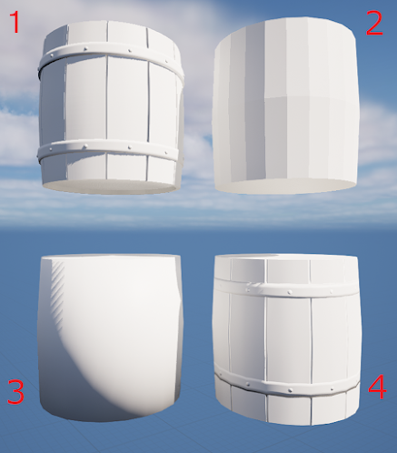
To show the results of our efforts, I set up a scene that demonstrates the effect of applying a normal map to the low-poly model.

1 - original high-poly model; 2 - 4 - the same low-poly model with different normal maps: 2 - no smoothing groups and no normal mapping, 3 - a smoothing group and no normal mapping, 4 - a smoothing group and a baked normal map.

Well, there is no doubt the high-poly mesh's shading on the first image looks really great without any normal maps applied. But if you consider that it uses 400K faces you wouldn't be very eager to use it directly in your game. The low-poly mesh has only 100 faces and it is really rough as seen in the 2nd sample that uses no normal maps too. The 3rd sample looks somewhat better adding smoothing groups and sharp edges. The 4th one is low-poly too but with a proper normal map and smoothing groups and it produces an amazing visual for a mesh of 100 faces. Normal mapping is a must-have optimization technique for modern games for sure. 

The topic of this tutorial is for sure covered in many other places on the Internet, but I wasn't able to find any single place that would answer all my questions and allow me to polish my own workflow. I aggregated all the necessary pieces of knowledge scattered over the Internet in this article to make the normal map-baking process with the latest versions of Blender and UE a walk in the park.


You can also read a fine article by Arthur Ontuzhan. Although that tutorial is a bit old and covers roughly the same topic, nonetheless the information it presents is still true and maybe his take on this topic will help you to even better understand the baking process. Also, there are a lot of links throughout this post to other great sources of information on normal map baking. Check them too if you feel the urge to dive deeper into practical and theoretical aspects of normal map baking.

Tuesday, April 4, 2023

Creating Fluid Sword Combo Animations in Unreal Engine 5.

Introduction

Hello dear reader! 

Today I would like to share with you some of my thoughts about authoring melee attack combos in games, their anatomy, different approaches to creating your animation assets for them, and implementing them in Unreal Engine. But before that, a short foreword explaining why I decided to explore this topic.

In 2003 Ubisoft released a superb game, one of my all-time favorites - Prince of Persia: Sands of Time. It was an absolute feast for my young gamer's senses. The story, gameplay, level design, VFX, animations, music... an ideal mix of high-quality ingredients.

I'm bringing up this game now because a couple of weeks ago I accidentally stumbled upon a video demonstrating the game's combat animations. And you know what? I was highly impressed with them once more, but this time from a whole new point of view. 

Shocking twenty years have passed since I finished this game last time. Today I'm a hardened veteran gamer and a game developer. And this is exactly why I reached a whole new level of appreciation for the superb quality of those combat animations. They were authored with staggering attention to detail and design. Check them out by yourselves. I am, personally, especially impressed with this basic attack combo. Those animated pauses between slashes are an embodiment of pure elegance itself. 

Demonstration of combat animations in Prince of Persia: Sands of Time.

Currently, I'm working on my own RPG game in UE5. For some time now I have been mulling over what type of combat system to implement. And after seeing this video I decided to use similar attack combos with animated pauses in my game. Now, that I'm mostly done with the implementation of this feature I want to put down a few words about this process.

Combo Anatomy

First of all, we are going to break down the anatomy of such a combo in terms of animations that are necessary to implement it. Let's assume that the combo consists of N attacks. The combo has to start from and end with an Idle animation. Between the combo attacks, the game waits for a player's input for a certain amount of time t_timeout. If the player makes no attack before t_timeout time is spent then we break out of the combo into the Idle animation. Each attack except the last one should have the same duration of t_attack so that the user can easily adjust to the combo's rhythm. The last attack is a special case of a Combo Closure Attack that can be, for example, slower but more powerful.

We can summarize all these details with a single Combo Animation Flow Diagram:

Combo Animation Flow Diagram.

Thus, to implement such a combo's animation perfectly and with full control we would need:

  • 1 Idle animation.
  • 1 Combo Closure Attack animation.
  • N - 1 Attack animations of t_attack duration each.
  • N - 1 Waiting animations of t_timeout duration each. These animations will seamlessly glue together Attack animations.
  • N - 1 Attack Cancel animation. These animations will seamlessly transition a character from the corresponding Waiting animation into the Idle animation when the waiting is timed out.

Showcase

I didn't make my own attack animations from scratch but used freely available animations from a great website Mixamo as a base for my combos.

I implemented two such combos for my game: one for a one-handed weapon and one for a two-handed weapon. And for each of these combos, I employed a slightly different approach. 

Slow and precise approach combo

For the first combo, I used 4 separate attack animations from the Mixamo. Each of these animations initially transitioned between states following a scheme Idle->Slash->Idle. The following week I had to do a really heavy animation editing in Blender to make these animations follow the scheme fitting my combo anatomy:

  • Attack 0: Idle->Slash1(0.7 sec)->Wait1(0.6 sec)->Idle.
  • Attack 1: Wait1->Slash2(0.7 sec)->Wait2(0.6 sec)->Idle.
  • Attack 2: Wait2->Slash3(0.7 sec)->Wait3(0.6 sec)->Idle.
  • Attack 3: Wait3->Slash4->Idle.

Finally I made an animation montage consisting of these 4 animations:


One-handed Weapon Combo Animation Montage.

BaseCharacterAnimation Blueprint Event Graph.

BaseCharacter.h


The main things to note here are "AttackEnd" and "ComboBreak" Skeleton Notifies. The AttackEnd Notify marks the start of the Waiting animation when a player might follow up with a new combo attack. The ComboBreak Notify causes the game to restart a combo from the very beginning when the next attack comes.

Fast and furious approach combo

For the second combo, I used an animation from Mixamo too. But this time I selected a single combo animation that follows a scheme Idle->Attack1->Attack2->Attack3->Idle. More than that, I did close to no preparatory animation editing. All the magic was done in the combo's animation montage:


Two-handed Weapon Combo Animation Montage.

Note that all animation segments in this montage reference the same single combo animation. The AttackEnd and ComboBreak Notifies work exactly the same way as in the first combo. But these animation segments are configured in a particular way to satisfy the combo's anatomy:

  • every segment ends at the animation time at which the following segment starts. Thus the combo's animation is seamless without any effort.
  • segments corresponding to attacks and waiting are of the same respective durations.
  • the source combo animation obviously does not have keyframes for transitioning back from each attack's Waiting states to the Idle state when the combo is broken. These transitions are made by UE automatically using Animation Blending. 
All I had to do to make an almost perfect combo montage from this single animation was to:
  1. select the correct points in time of the source animation at which to separate attack animations from waiting animations. I selected the frames between slashes where the legs' position was closest to the Idle state legs' position to make blending into the Idle state as seamless as possible.
  2. set up the segments' "Start Time" and "End Time" properties to these points in time. 
  3. scale the attack segments using the "Play Rate" property to the correct uniform attack durations. 
  4. similarly, scale the waiting segments. But to emphasize the effect of a character waiting for the player's input I made these segments from really short animation sections (~50 ms) and slowed them down ~8 times to uniform 0.4 sec.

And that is it! It took me exactly one evening to finish the second combo's montage. And the result is surprisingly good for such a short amount of time.

Conclusion

You can check out the WIP combos in an actual action for yourselves. In my opinion, each of these two approaches has its own pros and cons. 

Demonstration of implemented attack combos in my game.

The first combo with manually tailored animations looks really balanced and natural, it can be gracefully canceled into the Idle state after any attack. But it requires animation editing skills and time to fine-tune such animations.

The second combo, on the other hand, was really easy to implement. It saved me lots of time and effort. The result is of course not as perfect, not as graceful and natural as with a fully manual animation. But if you don't give it a really close look (because you are in the middle of a fast-paced sword exchange with several enemies) it looks pretty good. 

Automatic animation blending turned out to be a really great feature to speed up your game development and prototyping. This time I used premade animations as a base, but even if I had to manually create a new animation for a new combo, I would still prefer making one animation of the full combo following the Idle->AttackCombo->Idle scheme and upholding the roughly correct timings and between-attack poses that easily blend into the Idle pose, rather than doing 4 separate animations Idle->Attack->Idle and struggling to glue them together as a combo.

What thoughts do you have on this topic? Share your ideas, comments, experiences, struggles, and victories implementing attack combos in games down in the comment section.

Sunday, March 12, 2023

Rigid Body Animation Nodes

Random banter


Hello dear reader, long time no see.
While my SpaceStrategy project is on a halt ;) I'll take a liberty and post here some articles not related to the project specifically but to GameDev in general.

So, lately I've been polishing my Unreal Engine skills. This is a really great tool, may I say. BTW you can check some of the things I'm working on my YouTube channel. But my lightning-fast improvement stumbled upon a small stone on the way to the absolute UE-mastery summit. I would like to share this small challenge I encountered and write about a solution for it.

About Procedural Animation


There exists this amazing trend in modern GameDev called Procedural Animation. It encompasses lots of techniques like IK, Rigs, Layering, Blending etc. But today I'll say a few words about this particular technique when animation is created based on a physical simulation of collisions.

Say, you make a knight character and want to make a scabbard on his belt. And, for sure, it would be nice if the scabbard shakes and swings realistically when the character moves around doing various exercises like running, fighting, or dying... ahem. 

Of course you can add a few bones and simply make this scabbard swinging a part of all the knight's animations... You just need to keep in mind all premade animations, animation blends, procedural animations, modified animations... you see my point already, aren't you? Or you can make it so that the game's physical engine calculates the scabbard swinging dynamically for any kind of situation.

Rigid Body Animation Nodes


This particular technique in UE is called "Rigid Body Animation Nodes" or RBAN. I wouldn't dive into too minute details, but I recommend to check out the Epic Game's official tutorial on this topic

The main idea behind this technique is that the scabbard gets its own bone, but instead of animating it by hand, we assign collision shapes to the scabbard bone and all neighboring bones and add a constraint between them, so that the UE itself calculates the motion of the scabbard given its environment.


The tutorial I mentioned is superb and everything is crystal clear... except that it didn't work for me. My scabbard collision body stubbornly continued to ignore other collision bodies. I spent a whole day digging and educating on this topic, before I found the reason. The tutorial was lacking one crucial piece of information: one has to enable collisions between bodies by hand, otherwise they won't collide!


Lessons learned


In my last blog post I wrote that if you follow a tutorial and something doesn't work then chances are 90% that you didn't follow the instructions precisely. This particular case falls into the remaining 10%: tutorial didn't mention this detail. But the next lesson I would take out of this situation is the following:

"Before working on advanced tutorials, first work through basic tutorials on the topic because advanced ones are very likely to suppose that the reader already knows the basics."


Have a happy GameDev'ing evening.
Best regards.

Saturday, March 7, 2020

Struggling with new Unity NetCode.

Before pouring out my frustration at the universe I have to say a few introductory words. 

For more than a year now the Unity team is in a process of complete technology stack overhaul. And as a part of this process they are also remastering their multiplayer game packages. They call this new technology stack the "DOTS" (Data-Oriented Technology Stack). Because now it is in an active state of development there is critical shortage of tutorials and documentation. But it is expected that in the near future the DOTS will totally replace old Unity technologies (including networking packages, which are already marked as deprecated).

Now to the sad part. One of the reasons why I switched to Unity from my self-made game-engine was to make Space Strategy into a multiplayer game. When I just started my venture into the Unity networking I thought: "Well, either way, I know nothing about Unity networking, so why should I bother with obsolete technologies? I will just jump right into the new DOTS networking! It is alright that there isn't a lot of documentation and packages are still raw. I will manage somehow".

With that decision made, I:
And even with all that in place I have miserably failed to reproduce the simplest NetCube sample project while following the official tutorial. "Why, oh why doesn't it work?!!! Why there are no error messages anywhere?!", I repeatedly asked myself while comparing my project with the sample one line by line using diff tools.

Long story short, the bug was that entities that were expected to be synchronized between clients and server were not displayed anywhere at all! And the reason turned out to be that I have not installed Hybrid Renderer package into my project as was requested at the very beginning of the NetCube tutorial. That was because when I started the tutorial I thought: "I'll go as simple as possible and concentrate on the networking. Why do I need all the fancy rendering stuff at all?". But who would have thought that this package was absolutely necessary?

Lessons learnt (or reinforced) today:
  1. If one is using someone else's materials and failing, then in 90% of cases the blame is on oneself.
  2. If everyone on the internet except you successfully finished a tutorial, then follow the tutorial more thoroughly.
  3. If tutorial says "Add the A, B, C, and D packages", then, please, add all of them as requested.
Last couple of days I was desperately struggling to reproduce this NetCube sample. I have done it at last. But have I wasted so much time on such a silly mistake. Don't be like me :). Learn on other's mistakes and follow my Unity Space Strategy project on GitHub.


Saturday, January 18, 2020

Hello, dear readers!

Today I would like to share with you some tips regarding debugging the so called "Collection Was Modified Exception".
Often, this problem arises when a collection is changed during its enumeration with a foreach statement. The debugging is quite straightforward:
1) get to the problematic foreach statement;
2) set breakpoints in all the places in a code where the enumerated collection is modified;
3) run through the foreach body.
4) find the place of an unexpected collection modification.

But what to do if the collection modification is not so obvious or if the collection is modified in a lot of places? In these situations I prefer temporarily switching the enumerated collection with a special wrapper that is created with a sole purpose of identifying such a situation.

Lets consider a common System.Collections.Generic.List<T>. To create a wrapper that would automatically identify the "Collection Was Modified" situation follow these steps:

1) Create a stub for a new class ChangedDuringEnumerationMonitoringList<T> : IList<T> with an inner List<T> instance:
1:  class CollectionChangedDuringEnumerationMonitoringList<T> : IList<T>  
2:  {  
3:      readonly List<T> _list = new List<T>();  
4:  }  

2) Automatically implement all the IList<T> members by delegating to the inner _list. For example:
1:  public void Add(T item) 
2:  { 
3:      _list.Add(item); 
4:  } 

3) Implement custom IEnumerator<T> that delegates all its functionality to an original enumerator of a list and tells whether it is in a state of enumeration:
1:  public class NotifyingEnumeratorWrapper : IEnumerator<T>, IEnumerator  
2:  {  
3:      // An original enumerator that is delegated to.  
4:      readonly IEnumerator<T> _typedEnumerator;  
5:    
6:      // Injecting an original enumerator instance in a constructor.  
7:      public NotifyingEnumeratorWrapper(IEnumerator<T> enumerator)  
8:      {  
9:          _typedEnumerator = enumerator;  
10:      }  
11:    
12:      // A property that marks that an enumeration is in a progress.  
13:      public bool IsEnumerating { get; private set; }  
14:    
15:      public void Dispose()  
16:      {  
17:          IsEnumerating = false;  
18:          _typedEnumerator?.Dispose();  
19:      }  
20:    
21:      public bool MoveNext()  
22:      {  
23:          IsEnumerating = true;  
24:          return _enumerator.MoveNext();  
25:      }  
26:    
27:      // The rest of the implementation.  
28:  }  
29:  

4) And finally, modify your custom IList<T> implementation to check whether a collection is modified during an enumeration:
1:  class CollectionChangedDuringEnumerationMonitoringList<T> : IList<T>  
2:  {  
3:      NotifyingEnumeratorWrapper _enumerator;  
4:    
5:      public IEnumerator<T> GetEnumerator()  
6:      {  
7:          _enumerator = new NotifyingEnumeratorWrapper(_list.GetEnumerator());  
8:          return _enumerator;  
9:      }  
10:    
11:      public void Add(T item)  
12:      {  
13:          // Add this call for every IList<T> member that modifies a collection.  
14:          OnCollectionChangedDuringEnumeration();  
15:          _list.Add(item);  
16:      }  
17:    
18:      void OnCollectionChangedDuringEnumeration()  
19:      {  
20:          if (_enumerator != null) {  
21:              if (_enumerator.IsEnumerating) {  
22:                  // Setting a breakpoint here will stop a program exactly at the moment  
23:                  // that collection is modified during an enumeration.
24:                  System.Diagnostics.Debugger.Break();  
25:              }  
26:          }  
27:      }  
28:    
29:      // The rest of the implementation.   
30:  }  
31:    

Now you are all set to go. Switch the List type of your collection that has troubles enumerating for this new custom ChangedDuringEnumerationMonitoringList. Then run your application as usual to reproduce the "Collection Was Modified Exception". And the moment your collection is modified during enumeration your application will stop at the breakpoint. Now you can simply observe the stack trace and get straight to fixing your bug!

Having a custom list such as this in your toolbox makes detecting the source of "Collection Was Modified" problem as easy as two Copy/Paste to replace the collection type and one application run to reproduce the bug.

Feel free to take a look at the full implementation of the ChangedDuringEnumerationMonitoringList on my SpaceStrategy GitHub repository.

What are the techniques you are using to find the cause of the "Collection Was Modified Exception"? Please share them here in comments.